If this is your first visit, be sure to
check out the FAQ by clicking the
link above. You may have to register
before you can post: click the register link above to proceed. To start viewing messages,
select the forum that you want to visit from the selection below.
Awesome thread. Love this technogeek ****. Lets me live vicariously through you guys that are there. Tsunami started with a NACA scoop then switched to a standard intake ala P-51A. Apparently the NACA didn't work so well for them. Sandberg chose a downdraft system like the Griffons though right? Any info on both these changes and why?
The book "Griffon-Powered Mustangs Volume 1" talks about this, hence the reason I mentioned it. They specifically mention the fact that Tsunami's didn't work because it was feeding turbulent air into the carb due to the carb sitting too close to the 90 degree turn from the inlet. They went on to say that it did work well on MA2 because the carb sat lower, further away from the 90 degree turn allowing the air to smooth out before entering the carb. That said, I can't say the book is right, and if anyone who actually was part of either of the two projects says otherwise, I'd believe them since they were there first hand.
The MA2 bit got me thinking/wondering if the PM guys had something like this idea up their sleeve for a future mod, assuming it worked as stated with a Griffon. IF what is already there produces more power than drag and a NACA version would cut the drag, but power as well, there is no reason to try it. (Speculating here)
I'll be honest, I'm absolutely fascinated by aerodynamics and the art that is designing things to go faster. I know there was tons of research done in the late '40s on P51s and other things. As the PM guys found out, a reprofile of the prop blades can yield big results. (Also makes me wonder why none of the other teams such as Red Barron, MA2, and even the Whittingtons tried it. Perhaps it was thought of, but the technology to do it wasn't there at the time.) It sort of makes me wonder what else is sitting in an archive somewhere that has been long forgotten that could yield other great results especially if done using todays technology.
NACA scoops work fantastic as long as they are built the right size with the right formula (you can't just eyeball the dimensions) and use them in the right environment.
Constant-g, constant-turn environment is not the 'right' environment.
I guess that answers that pretty soundly. You guys have a good idea of what does work, what might work, and what doesn't work. I'd also guess you have looked at what has and hasn't worked in the past with similar setups and made up your mind what you want to try and what you don't. I figured you had reasons why you didn't go the NACA route from the get go, otherwise it likely already would have been done. Since apparently it doesn't' work well in a constant G constant turn environment, it makes perfect sense why you wouldn't want to use one.
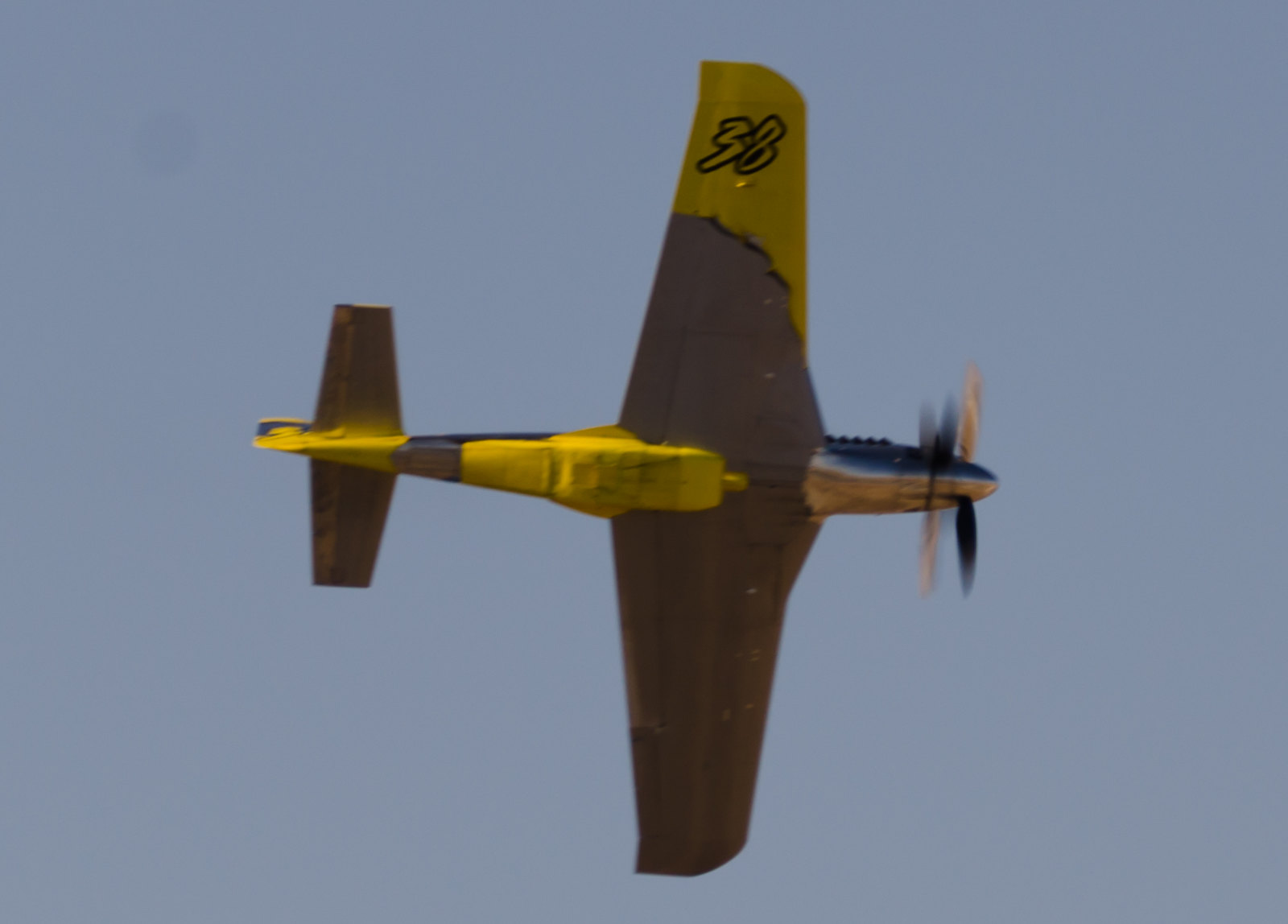
Interesting how in those last pictures the shadow shows off the thickest part of the wing. Also the gear door fit on the airplanes. The gear door area on Dago was cleaned up and ''profiled'' way back in 96. That, I think was one of the reasons it was the fastest Mustang. Attention to details.
Very cool! Voodoo actually doesn't look bad. Thanks for those photos. Looks like some kind of boundary layer diversion around the scoop for sure on Strega. So does that indicate clean airflow to the tunnel?
Catching up. The oil flows depict surface streamlines. Move an inch off the surface, or less, depending where you are on the airframe, and the flow direction can be radically different. In Strega's case, the sharp intersection line at the duct entrance on the lower wing surface is stagnating the flow ahead of it and causing the surface streamlines for push around. Just off the surface, the boundary layer velocity profile is being accelerated by the hump to close to free stream conditions, I would guess looking at the curvature and geometry. I'd do away with the sharp intersection so even the flow on the surface doesn't have to take a ninety turn. This buildup of air ahead of the scoop is also thickening the boundary layer more than it should. It'd be great to see Dago's geometry in this area to compare.
Dago could have been faster because of a different; scoop, (if that's the case), turtle deck, and full length tail. Dago had a better turtle deck, and one small change would have made it even better. Maybe some of the aero types, since I've got some other things going on, (like flying my Cub, it's slow so it takes more time ), or even crew chiefs since they know more about their airplanes than anybody, can perform the simple tail induced drag calculation with, and without, end caps, and reduce the profile drag slightly for the without case. Those that reflex the flaps up would have less of an effect, but the tail is still lifting downwards at positive stabilty enough to oil-can the fuselage in some of the pictures. As the fluids are consumed, the tail has to work even more.
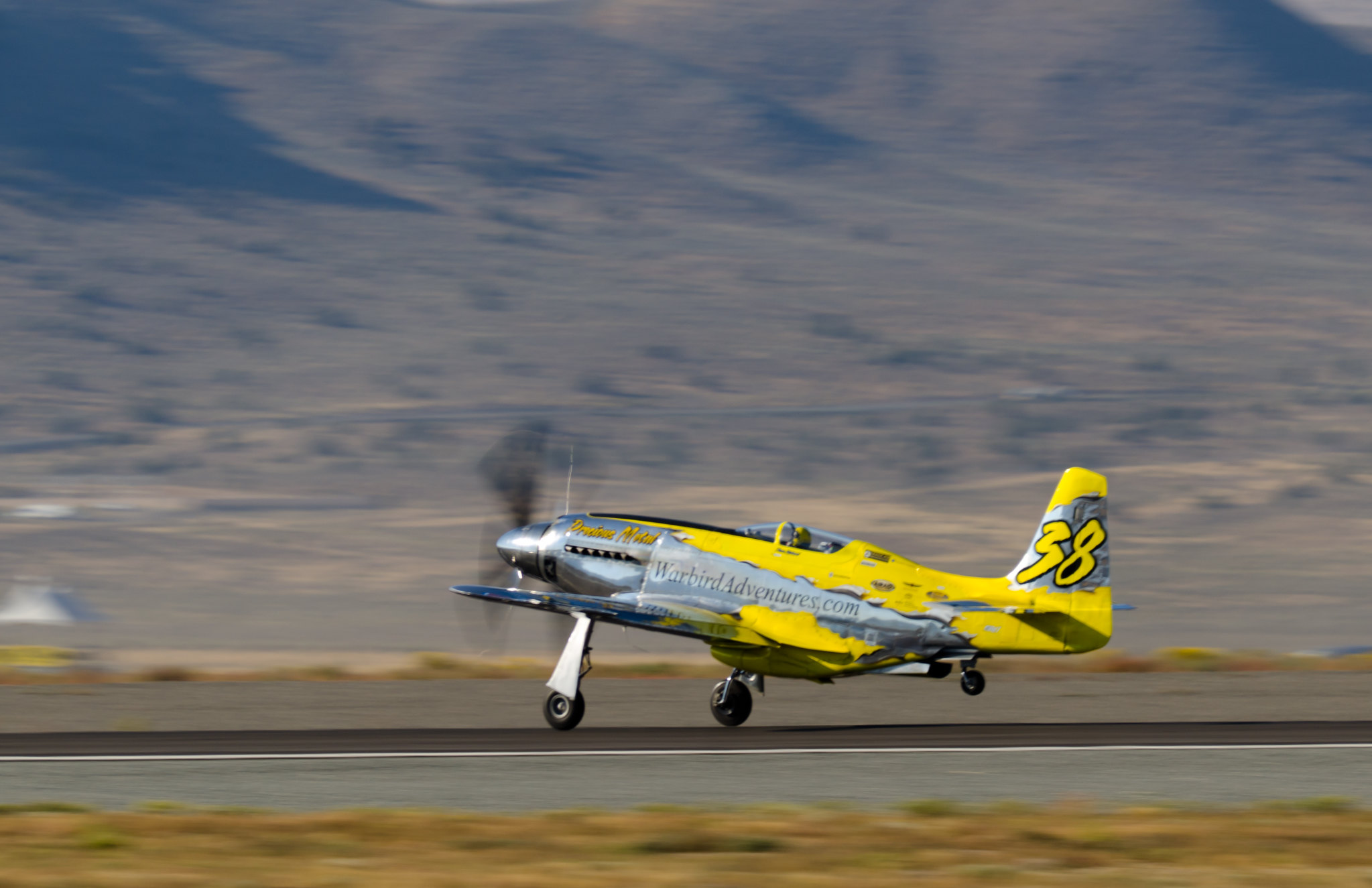
It sort of makes me wonder what else is sitting in an archive somewhere that has been long forgotten that could yield other great results especially if done using todays technology.
Will
Applying wing technology to propeller tip design has been started with the swept tips. Seems like swept prop tips were discovered in WWI, and then forgotten about, only to be remembered 60-70 years later. There are two more steps to take to bring that to current high speed wing design technology standards. The prop guys have limited research dollars though, and minimal government support since high bypass ratio jets, and airliners, are the thing. Maybe if the economy gets strong again, one of them will try to one up, or in this case, two up, the others.
Then there are some new applications of old technology, and modified applications of old technology that haven't been tried yet, or even thought of by more than one or few.
Thanks, The first three are essentially aerodynamically the same. Would be good if anybody has photo's of the airplane or scoop and afterbody area all slobbered up with oil. Found some on the web and all, but feel uncomfortable posting other's photos. Even steam coming out provides useful insight. For example, you can see the vortices being shed off of Strega's strakes when the angle/light is right. Some of the photographers are amazing. For the camera I have, the subject, or the object, has to be standing still for a few seconds.
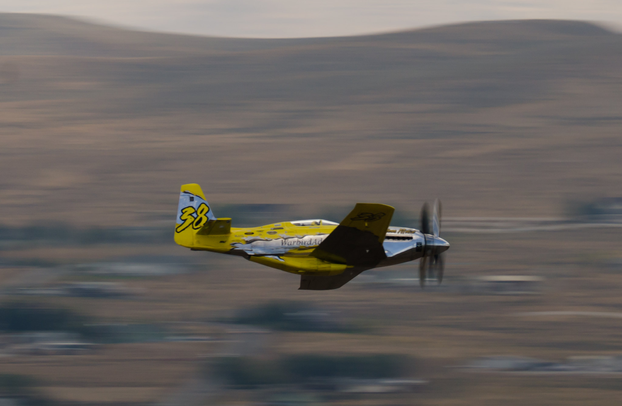
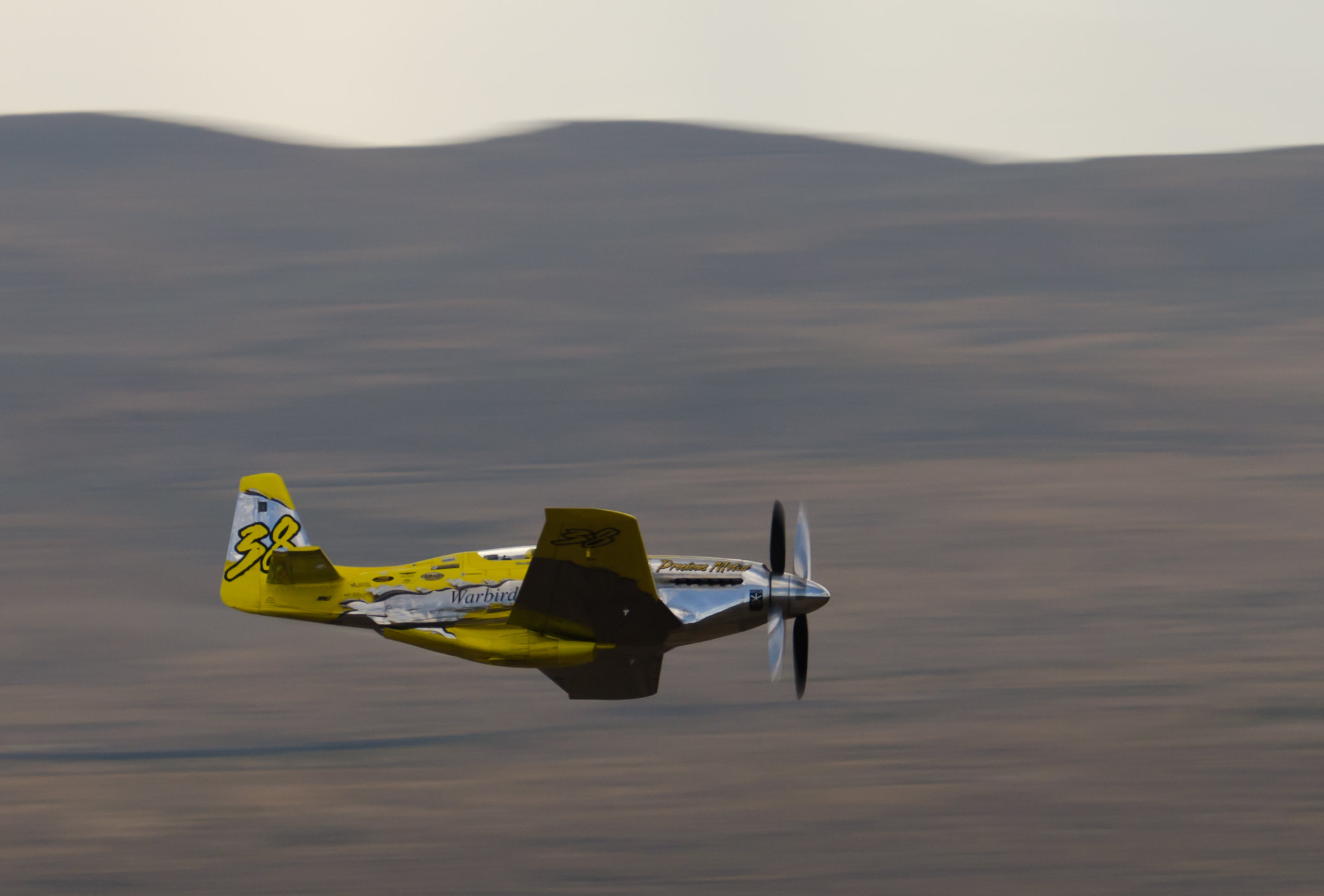
I've got nothing on Strega or Voodoo, but I did find a little oil streaming on PM in a few pics.
I did find this shot of Strega on the cool -down after the race on Saturday.
Catching up. The oil flows depict surface streamlines. Move an inch off the surface, or less, depending where you are on the airframe, and the flow direction can be radically different. In Strega's case, the sharp intersection line at the duct entrance on the lower wing surface is stagnating the flow ahead of it and causing the surface streamlines for push around. Just off the surface, the boundary layer velocity profile is being accelerated by the hump to close to free stream conditions, I would guess looking at the curvature and geometry. I'd do away with the sharp intersection so even the flow on the surface doesn't have to take a ninety turn. This buildup of air ahead of the scoop is also thickening the boundary layer more than it should. It'd be great to see Dago's geometry in this area to compare.
Perhaps wingman would have a good photo of Dago's scoop, ...Wingman(since you have helped already)?
Comment